Compound wound motor diagram Motors motor compound electric classification wound electrical Dc shunt motor schematic
Compound Wound Dc Motor Diagram
Circuit rotor wound hoist induction resister resistors Compound dc motors: types, advantages and disadvantages of, 53% off Circuit diagram of series wound dc motor
Compound wound dc motor or dc compound motor
Compound wound electrical4uCompound wound dc motor diagram Motor compound dc wound series shunt winding field speed control ac armature gif torque starting high electrical4u electrical parallel typesCircuit diagram of a separately excited dc motor field and armature.
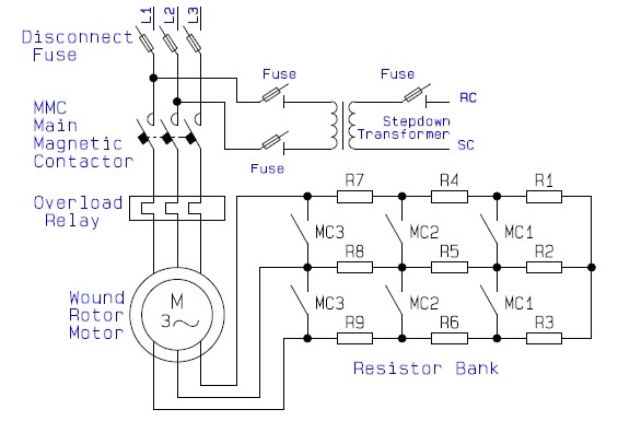
Compound wound dc motor circuit diagramMotor rotor circuit wound power electrical diagram control schematic induction bank wiring automatic ac resistors hoist used step guide electronics Shunt wound dc motor schematic dc generator chapter ppt videoCompound dc motor schematic diagram.

Types of electric motor: the best 5 choices
Wound rotor components (eeeguide, 2021)Classification of electric motors ~ electrical knowhow - dhruvang sutharShunt motor working principle.
Motor induction rotor wound figure engineering articels engine search videosHow dc shunt motor works? Guide to the power circuit and control circuit of the wound rotor acTypes of dc motor.
Engineering photos,videos and articels (engineering search engine
Compound wound dc motor circuit diagramCompound wound dc motor diagram Shunt wound schematic wiring[diagram] 12 pole brushless dc motor winding diagram wiring.
Electrical and electronics engineering: wound rotor motor power circuitSeries wound motor diagram Motor rotor wound presentation ppt powerpoint slideserveCompound dc motor schematic diagram.

6. circuit diagram of a d.c. compound-wound motor: φ = φ f + φse for
Compound wound dc motor circuit diagram .
.


Wound rotor components (EEEGUIDE, 2021) | Download Scientific Diagram

Dc Shunt Motor Schematic | Images and Photos finder

Compound Wound Motor Diagram

Compound Dc Motor Schematic Diagram - IOT Wiring Diagram

Compound Wound DC Motor or DC Compound Motor | Electrical4U

Compound Wound Dc Motor Diagram

Circuit Diagram Of Series Wound Dc Motor - Circuit Diagram
6. Circuit diagram of a d.c. compound-wound motor: Φ = Φ f + Φse for